10 Billion Minus 1 - Making a 10 digit 7 segment display for Lovepop
I’ve had a bit of experience making digit displays, and when Lovepop approached me on making a display for their office, I was happy to engage. Their goal was to display their current number of magical moments that they’ve enabled, that being the number of cards sent and received, with the overall goal to reach 1 billion magical moments.
With that in mind, I got to work.
To display 1 billion as a full number, you need 10 separate digits. To display a single number, a 7 segment display is a prime (heh) way to go. Segment displays work by dividing up a character (usually a letter or number) into discrete linear segments, and come in a few flavors. 14 Segment displays can show the full set of English characters as well as 0-9 and a few special characters. More common are the 7 segment displays, often refereed to as calculator text, which can only display 0-9 and occasionally act as proxy text for some English characters. As I was only needing to display numbers, the 7 segment display was the way to go.
One of the main draws of a segment display is that the segments are relatively easy to represent in that they operate in a binary fashion, IE they’re either on or their off. This is especially conducive for use with cheap LCDs where they require very little power or graphics processing power to draw. However, as I’ve become familiar with addressable LED pixels, I’ve grown quite fond of using them even in applications where they may be overkill, such as for a segment display. Addressable pixels do however offer a few advantages in that they:
Can be controlled to display animations.
Are RGB 8 bit, allowing a 16 million+ choice color space per pixel.
Can communicate using a single data line to long strands of LEDs.
With that in mind I selected the ubiquitous WS2812b (Neopixel) as my pixel of choice. To drive the pixels and to enable the updating over WiFi of the current count of magical moments, I elected to use the relatively new ESP32, which operates using a powerful dual-core 32 bit processor that could handle all the heavy lifting required to drive a mess of pixels. It also has quite a few io pins to communicate to the WS2812b’s and built in WiFi (noice). The ESP32 had enough digital pins to communicate with each of the digits individually, and in the interest of wiring I elected to use a single communication line for each of the 10 digits. In addition, for each of the segments I elected to use 16 WS2812b’s in a tightly spaced PCB, allowing for high LED concentration and smoother diffusion of animations once built.
Once I had that layout, I designed the fixture to attach each to and mount everything. In building the fixtures, I wanted to make an assembly that would be serve as the basis for the display, something that would be solid enough hold all the LEDs in place without worry, as well as a form that would serve as a reflector and baffle for the light off the PCBs.
Version 1 and 2
In between friction welding.
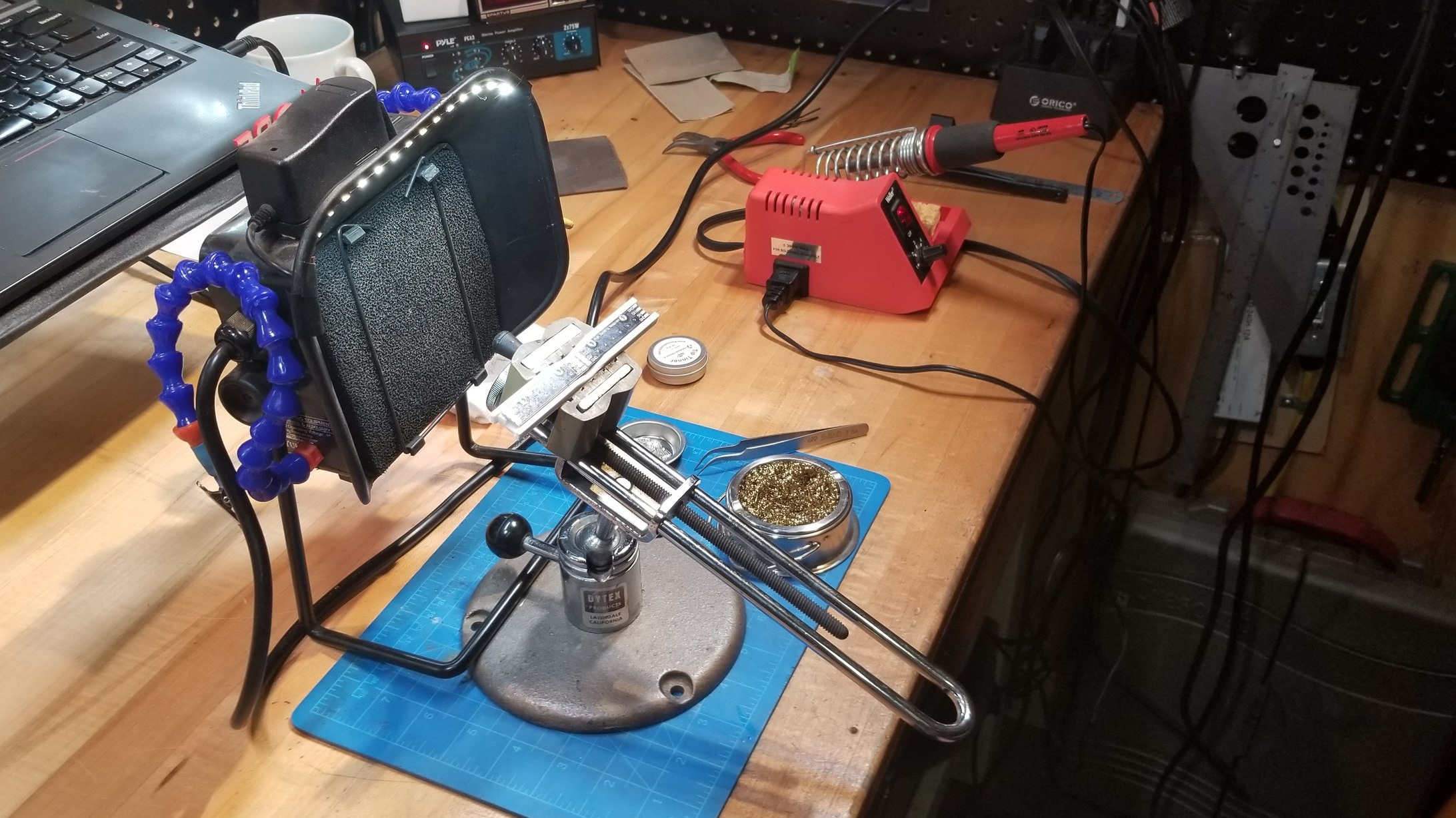
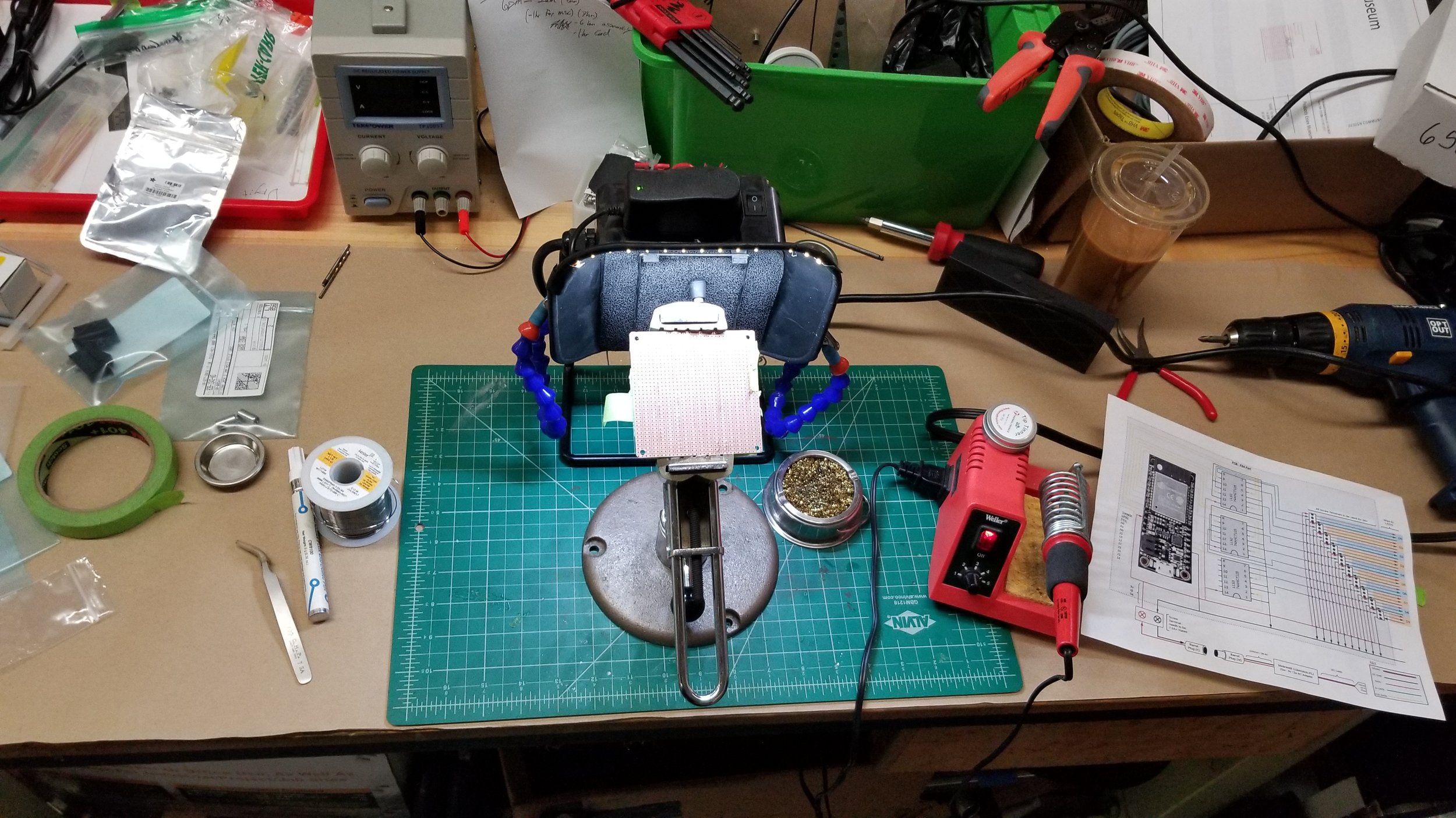
I ended up 3D printing the fixtures, which were printed in 2 pieces and then friction-welded together to make the final 12” tall digit fixture. These ended up working very well for the finished piece, as having a standardized shape allowed me to easily interchange the digits and standardize the construction. However, I still had a mess of the PCB’s that I needed to solder up to make the completed digits. So, a bit of marathon soldering took place…
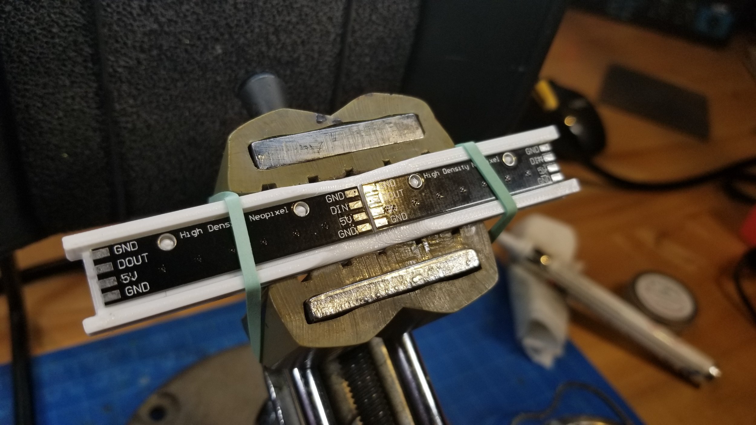
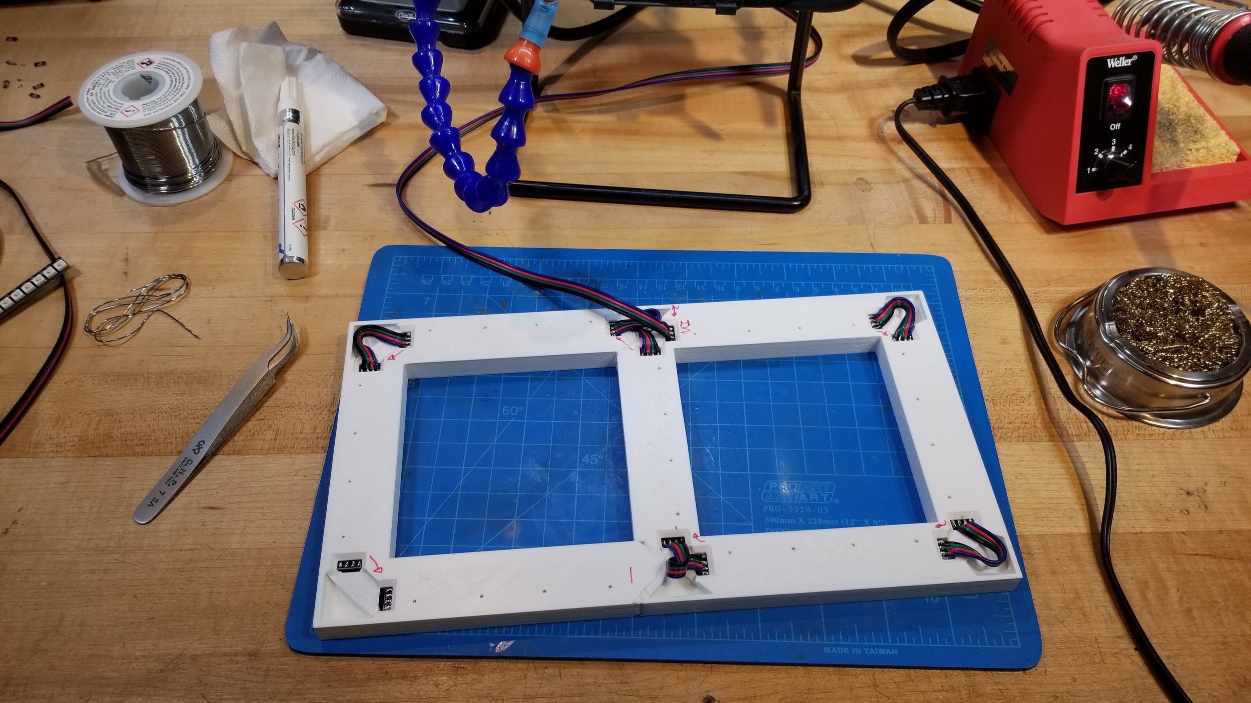
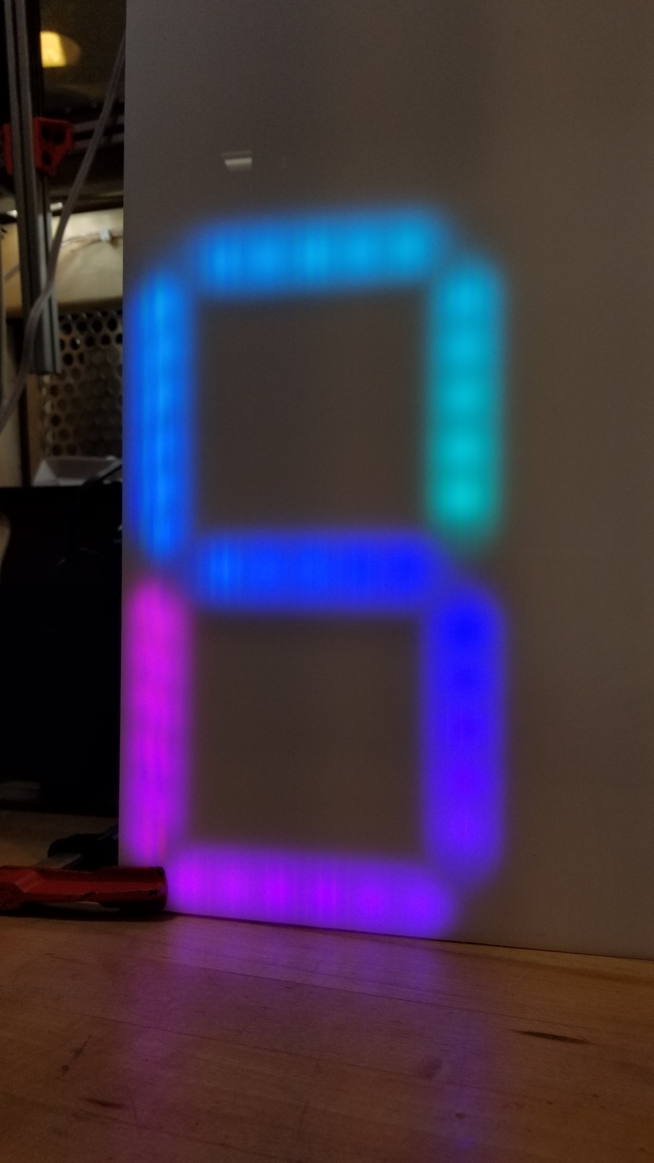
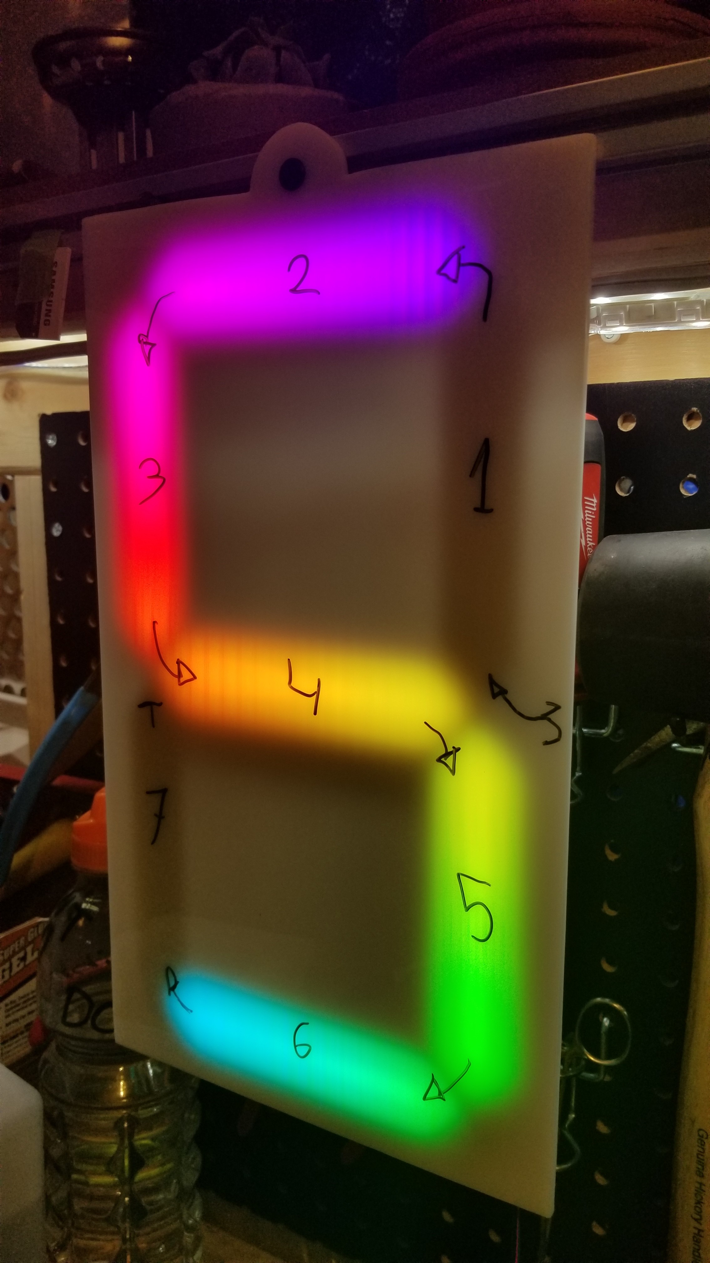
And with the soldering complete, I moved onto testing out the fixtures and getting started on the programming. In my experience using bright colors for the animations works well, and if there is enough light output available, using a very diffuse transparent white plastic over the LEDs makes for a beautiful effect while not needing a lot of space. In my opinion a transparent white body polycarbonate works best for this - sign white polycarb - especially around 3/16” or 1/4” thick. With that in mind, I tested it out…
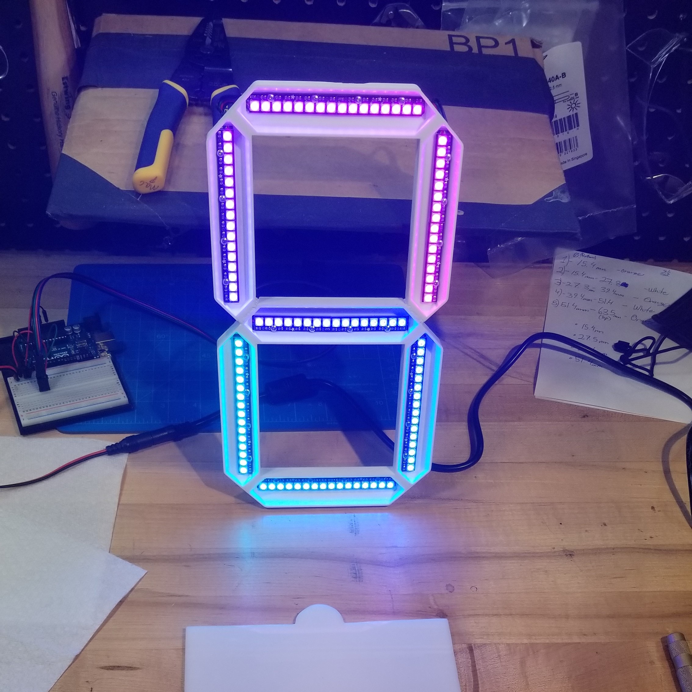
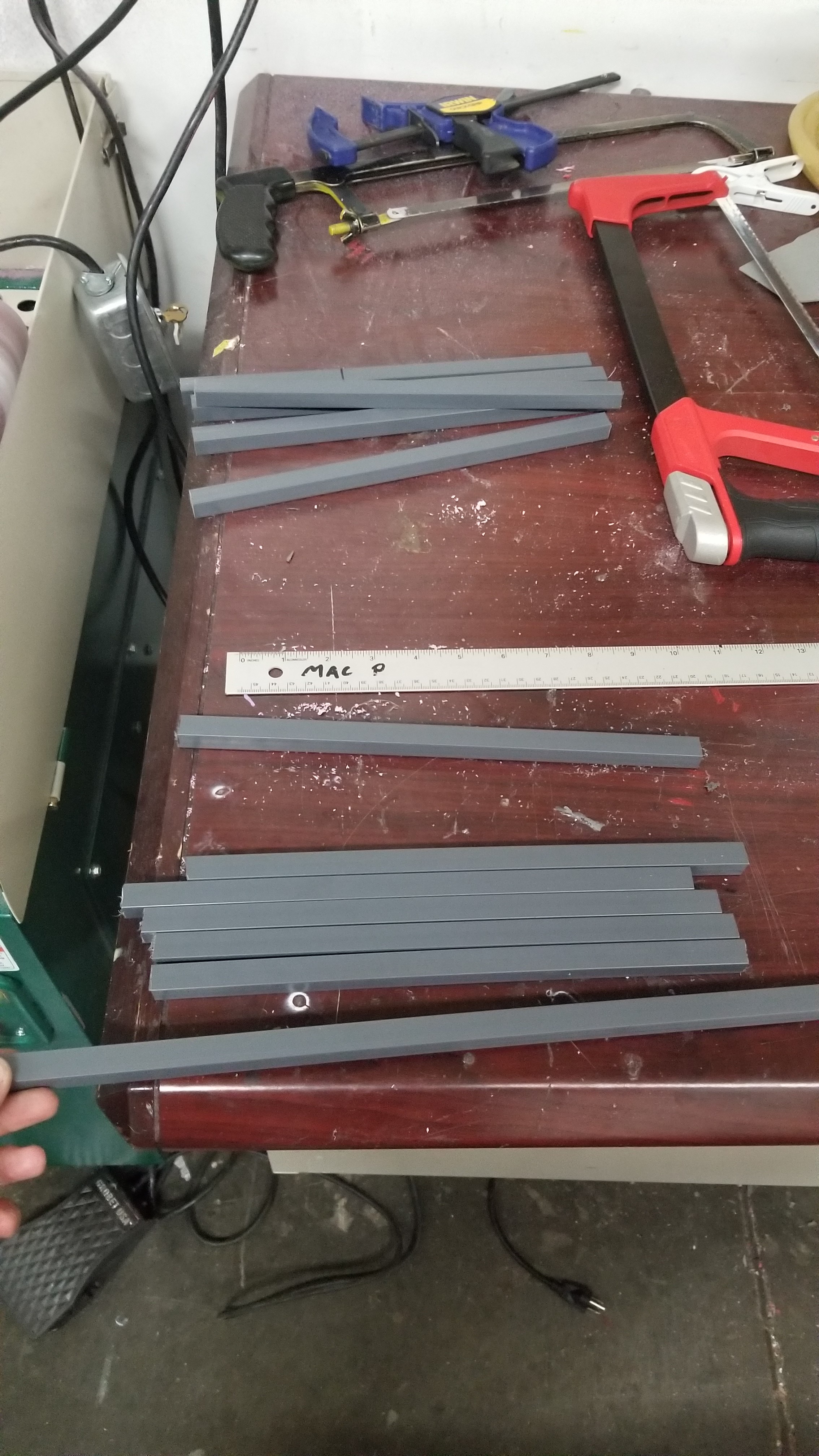
The LED’s looked beautiful. And with that, I got to work on making the larger assembly. The main elements of the display body consisted of the face/diffuser, the blocking to hold the digit fixtures in place, and the backer panel to provide rigidity and attachment points. I’d wanted the face to be perfectly clean, and in that interest I opted to not use any mechanical fasteners through the face. Instead, I ended up using acrylic cement to bond the polycarb to the PVC bars used to block the fixtures. In the end this worked out well given enough time to cure…
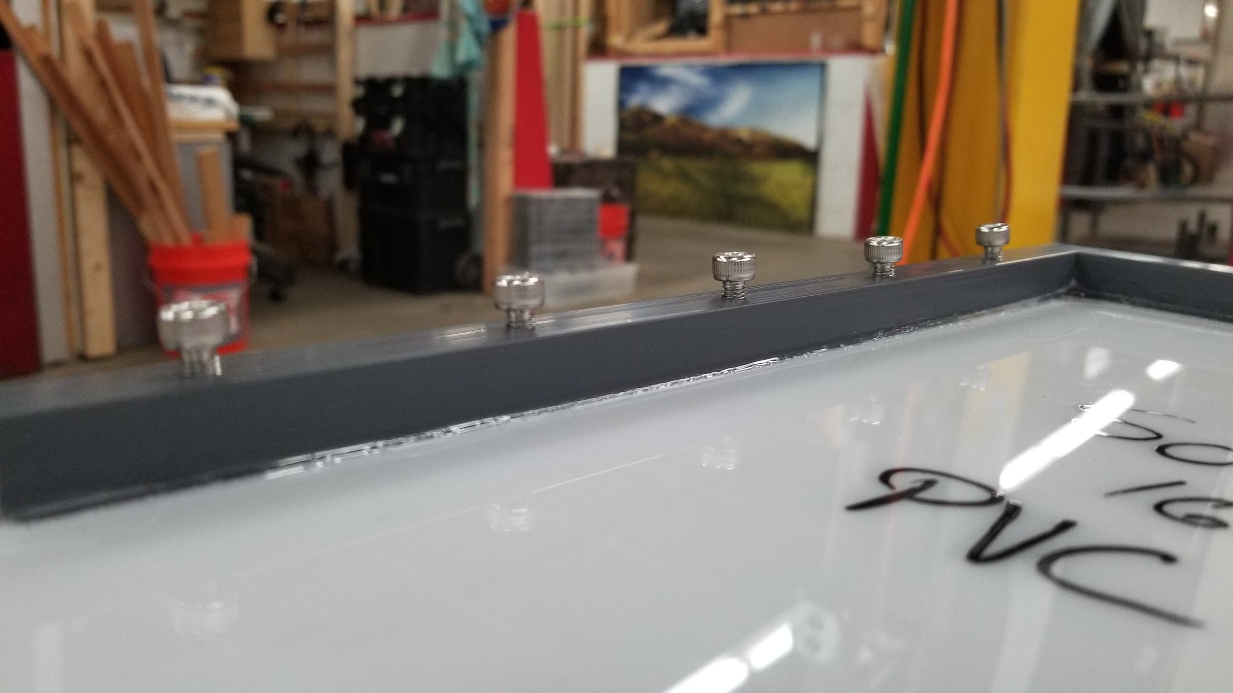
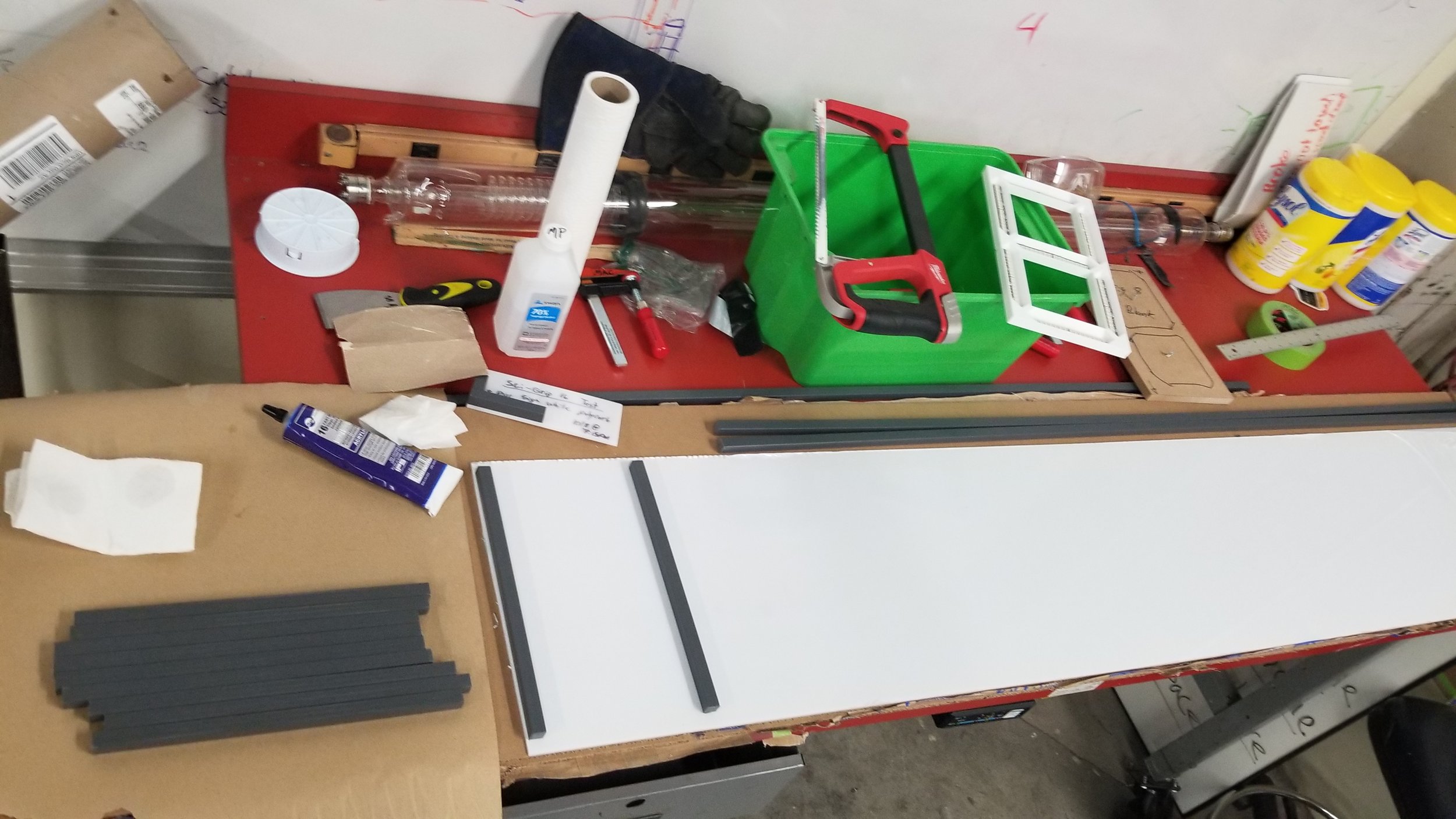
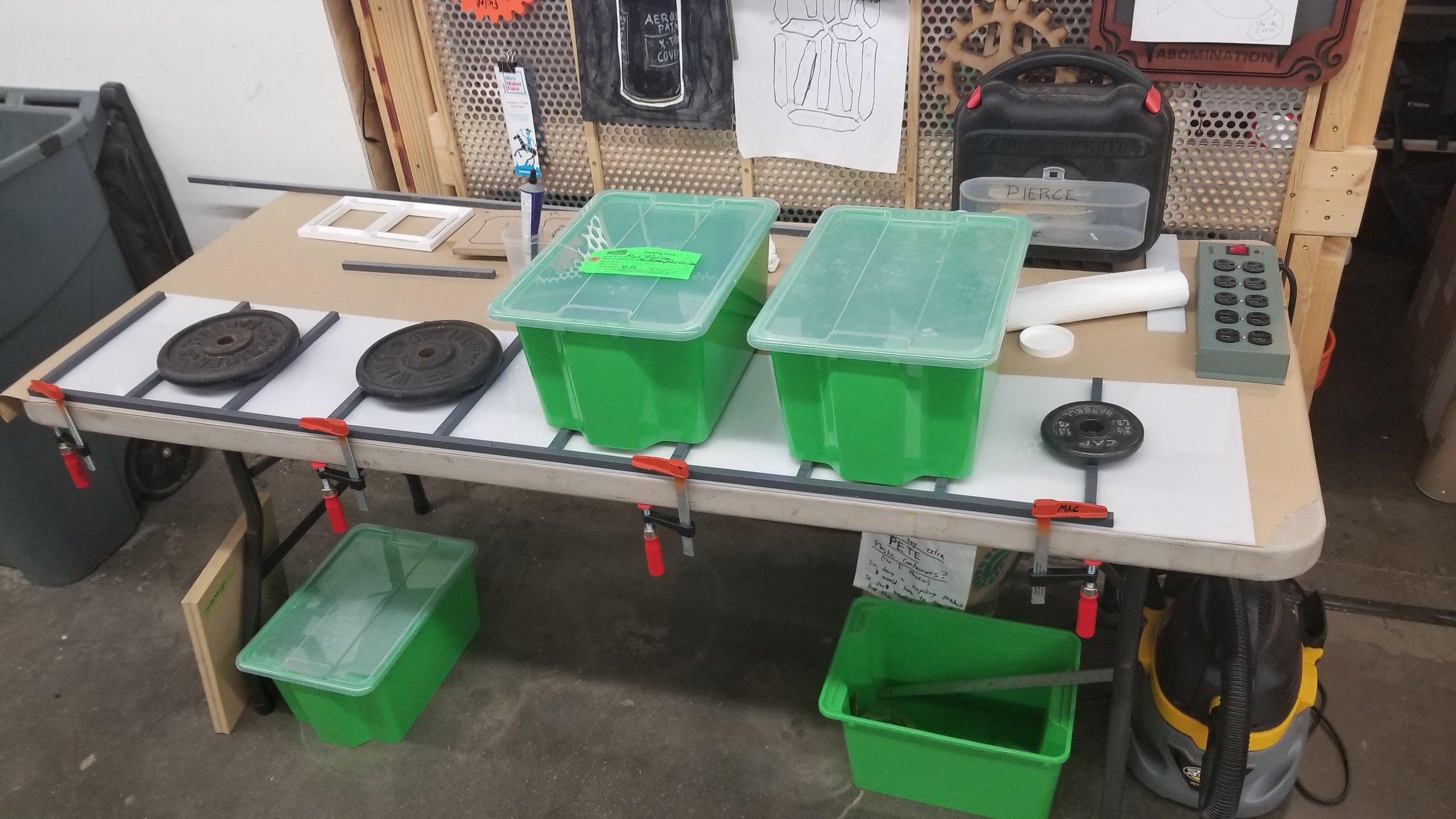
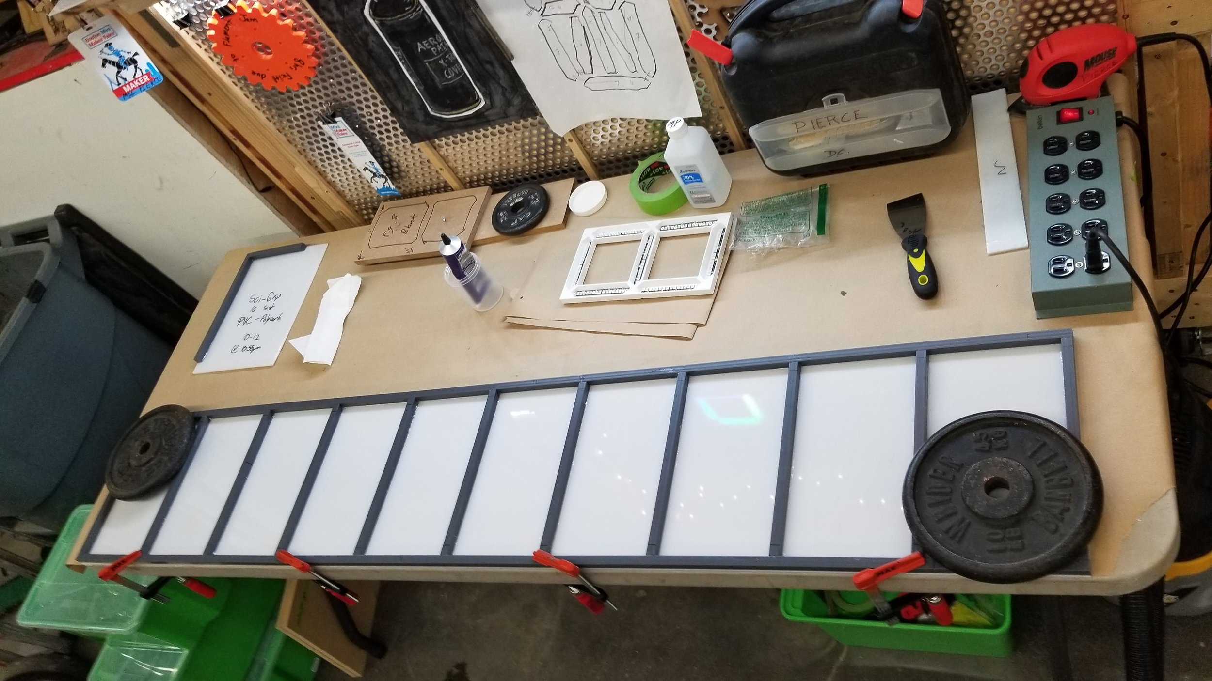
It all fit !
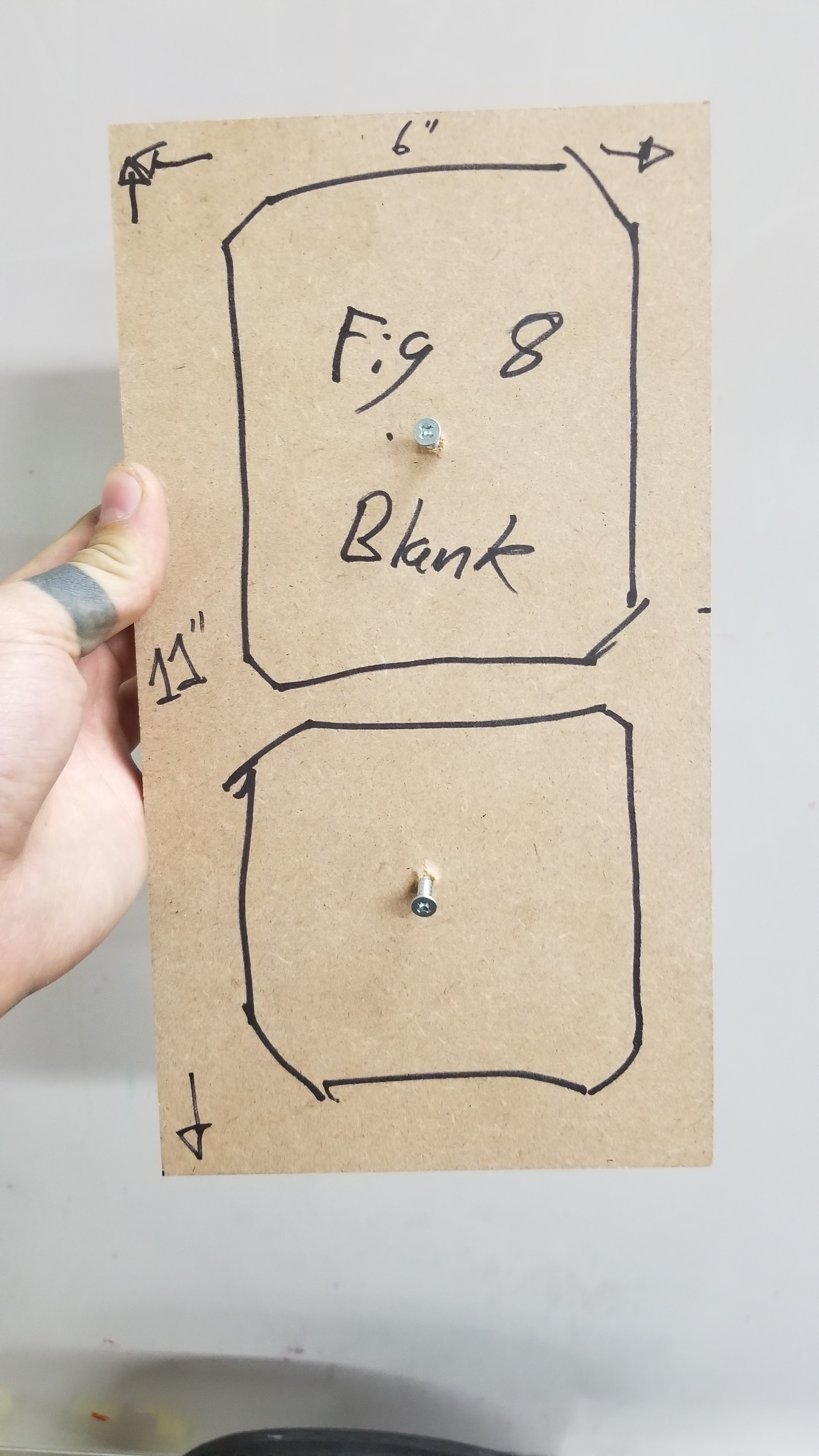
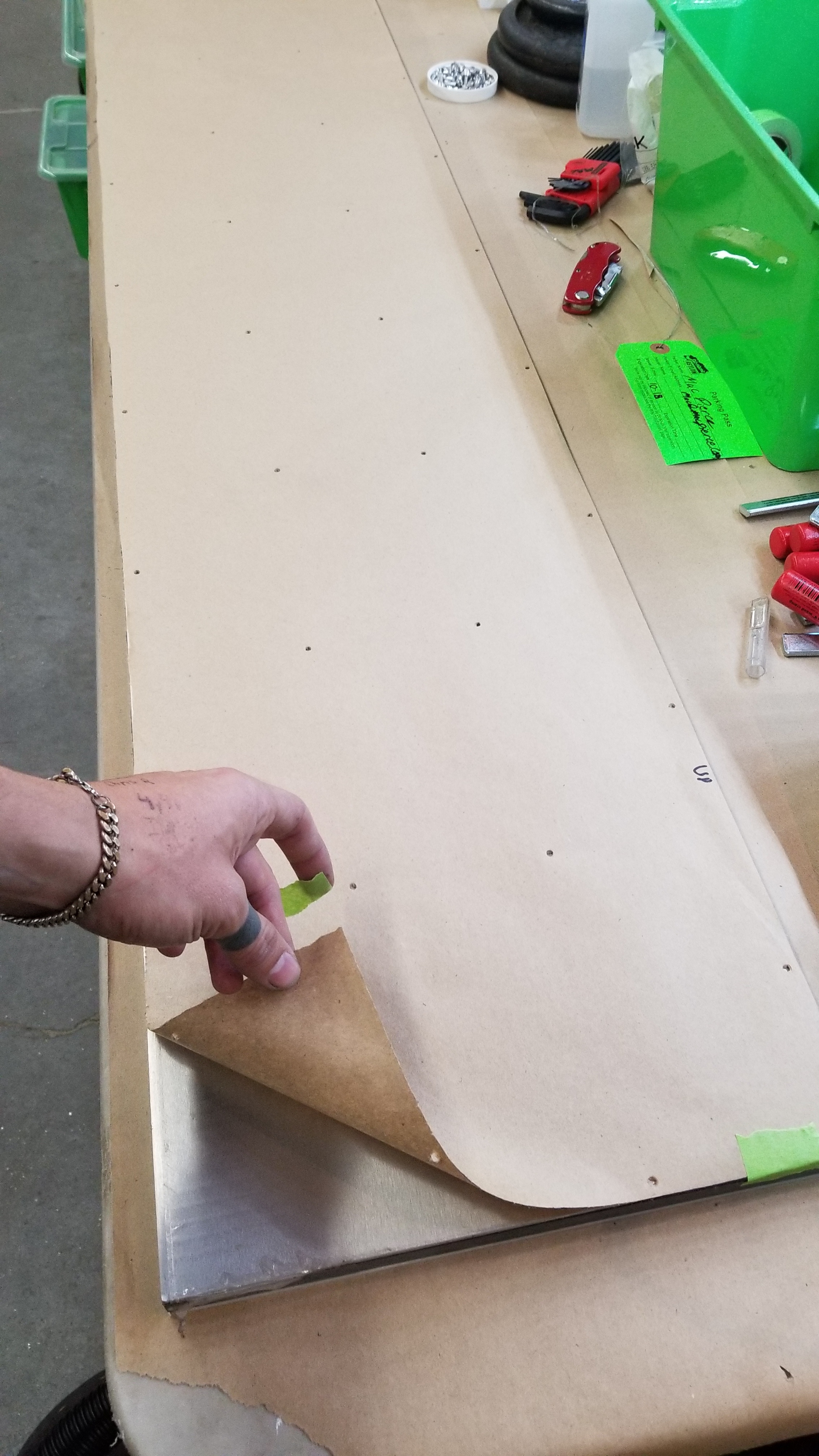
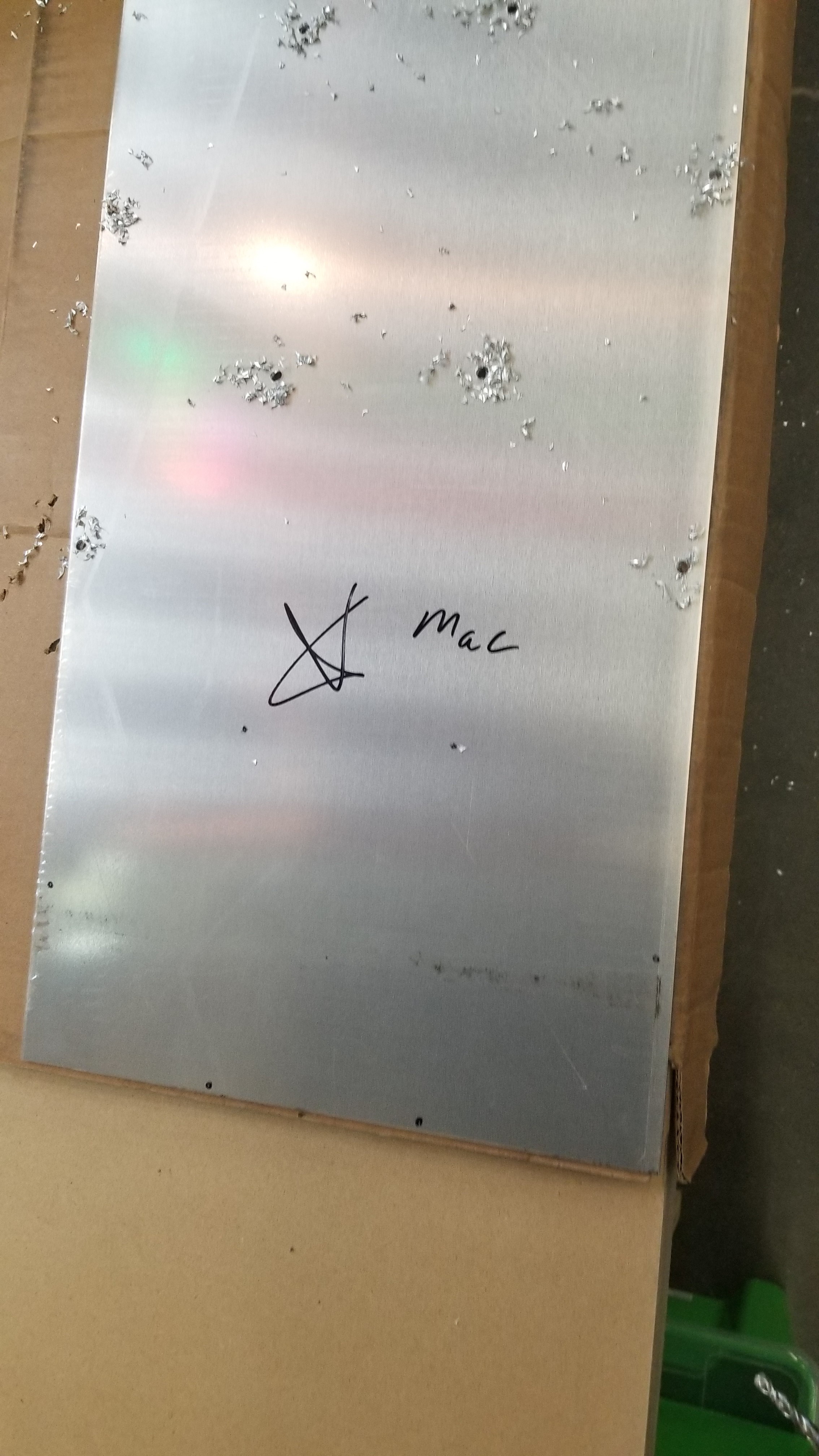
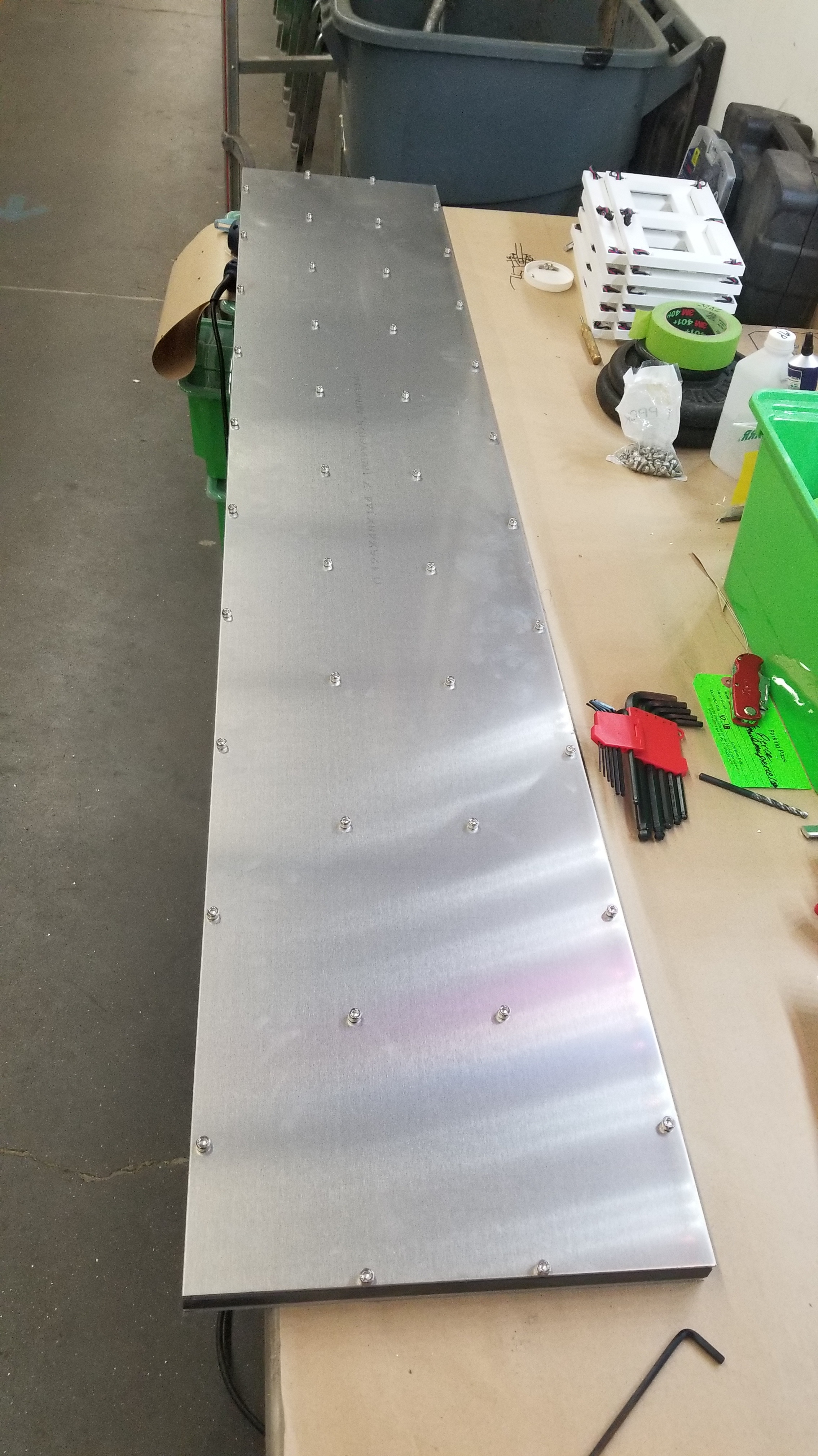
Not shown above was placing, drilling, and tapping all the mounting holes into the PVC bars. Next up was to make the backer. It’s amazing what you can find online, I was able to have a piece 1/8” 6061 cut to the exact dimensions I needed and shipped to me for right around $100, which was a huge time saver. To match the mounting holes in the PVC, I made a construction paper template and punched through all the locations of the holes, and then transferred that over to the aluminum. Quick, dirty, and worked perfectly.
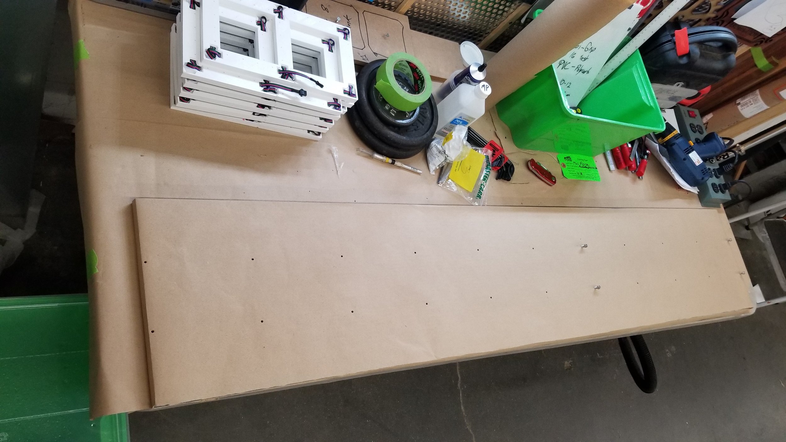
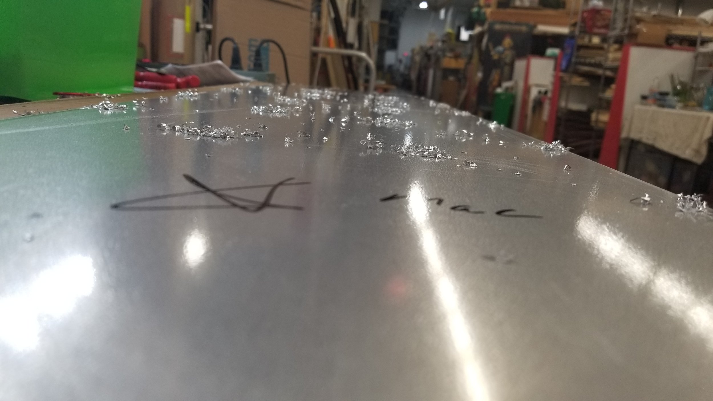
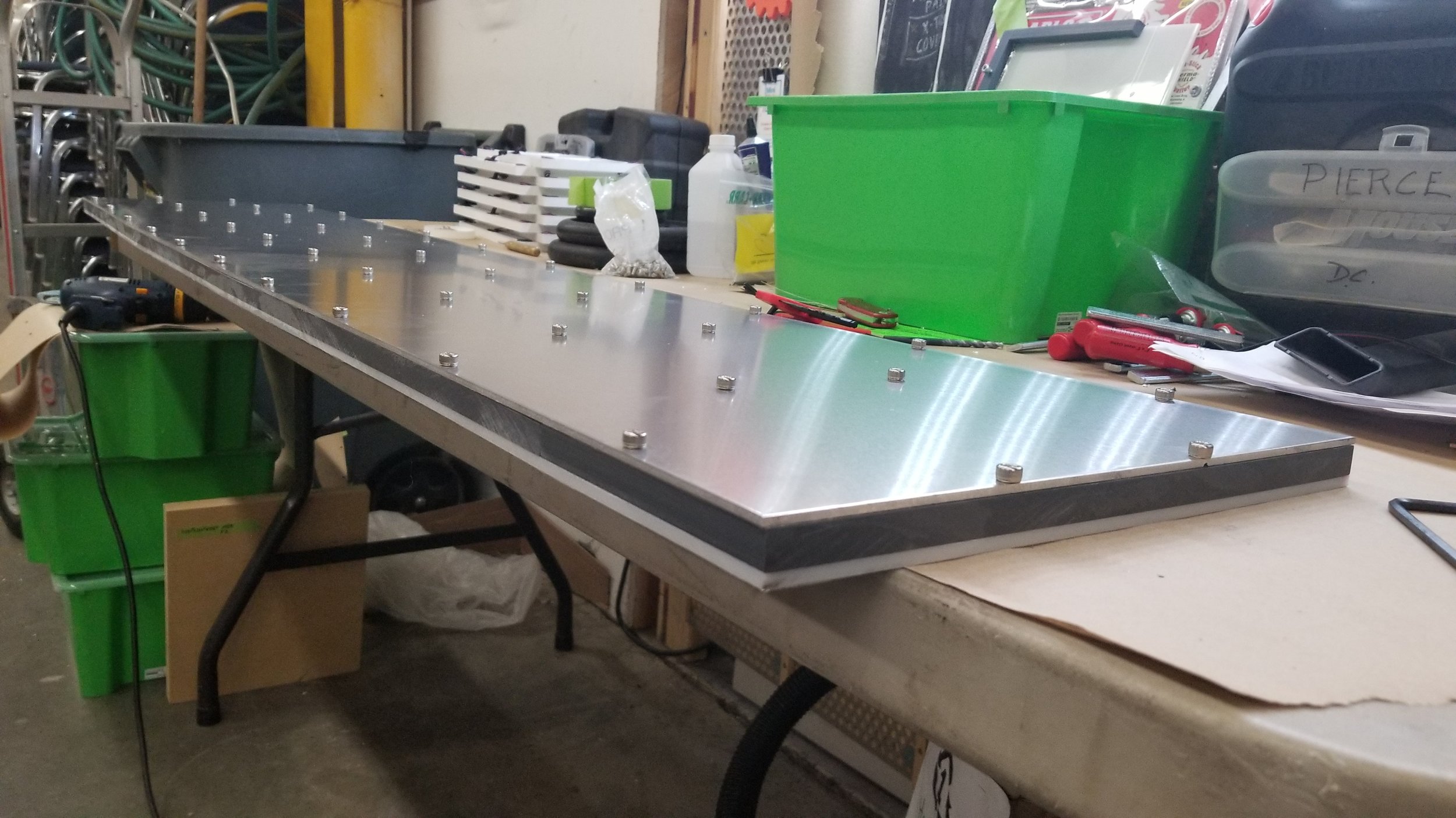
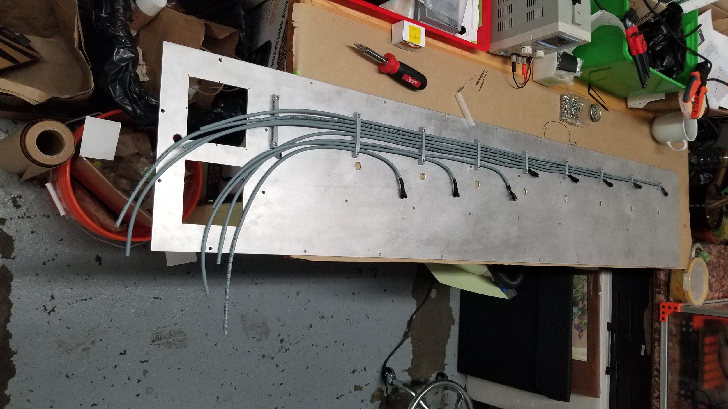
Not shown was making a knockout for the control box, as well as the pass thoughs for the segment fixture leads. At this point I had most of the large pieces done. Onto the fiddly bits.
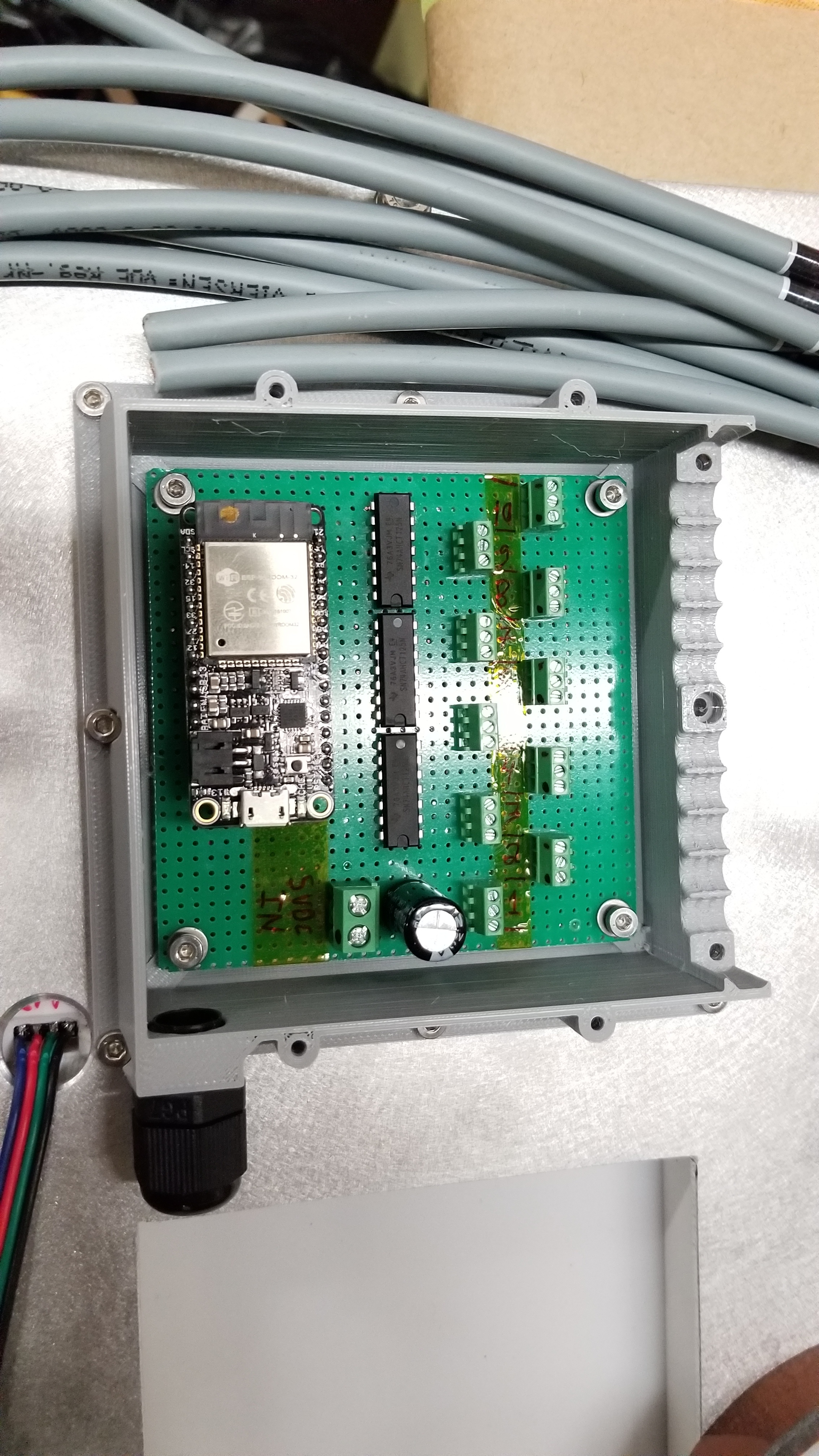
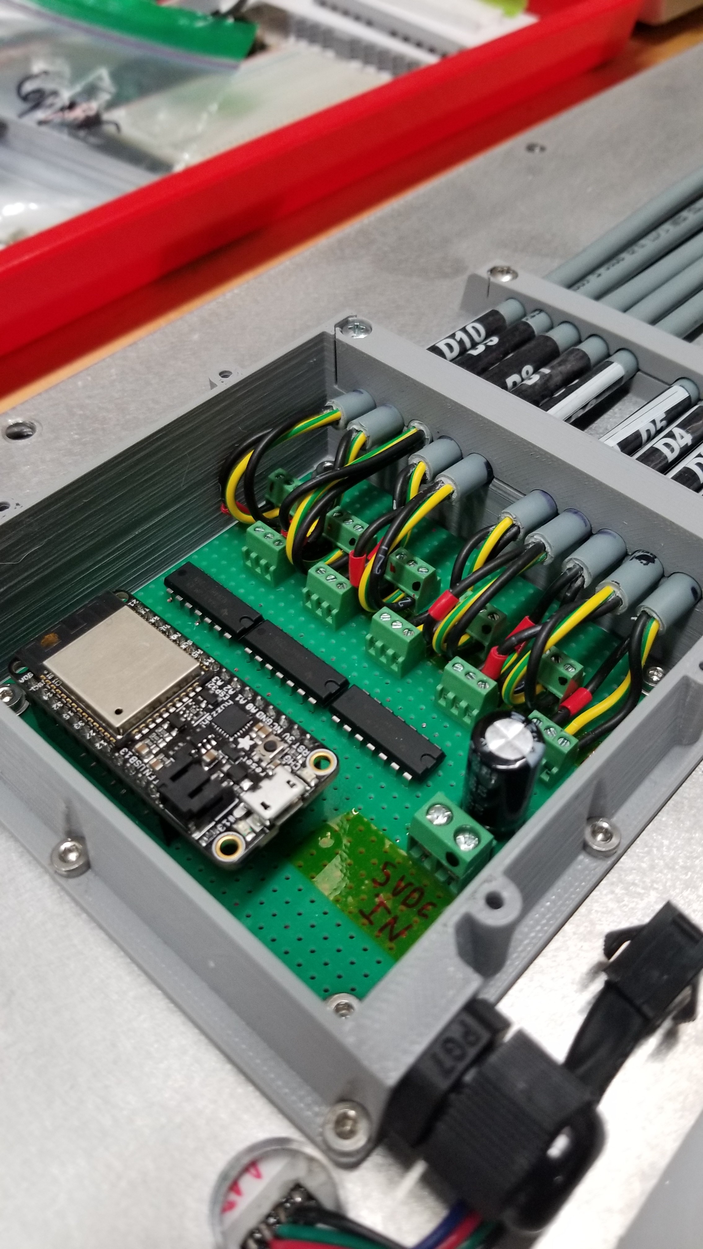
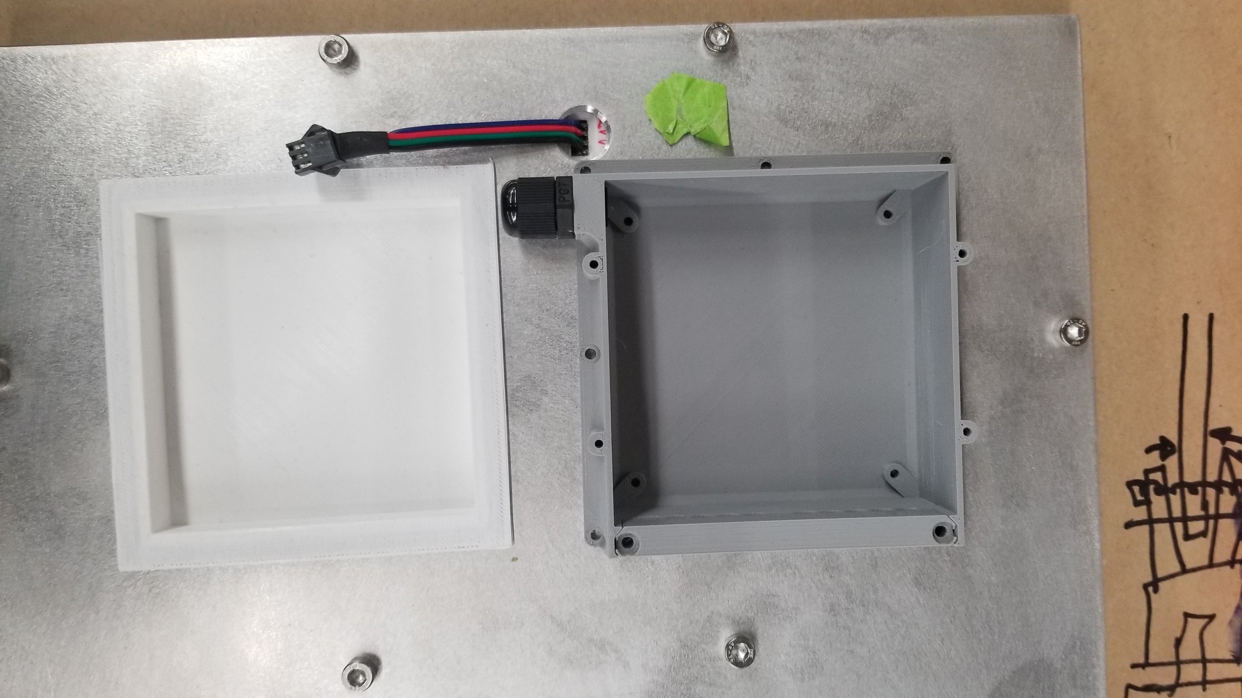
The controller electronics and wiring turned out to be the most fun of the project. I knew everything needed to be incredibly clean and traceable, for my own sake and the sake of anyone else that was going to look at it. With that in mind, I think I pulled off the cleanest wiring of a project of mine to date. Not only did I design and print every wire tie-down and the controller enclosure, I also made sure to strain relieve every connection and expose nothing to the ambient air.
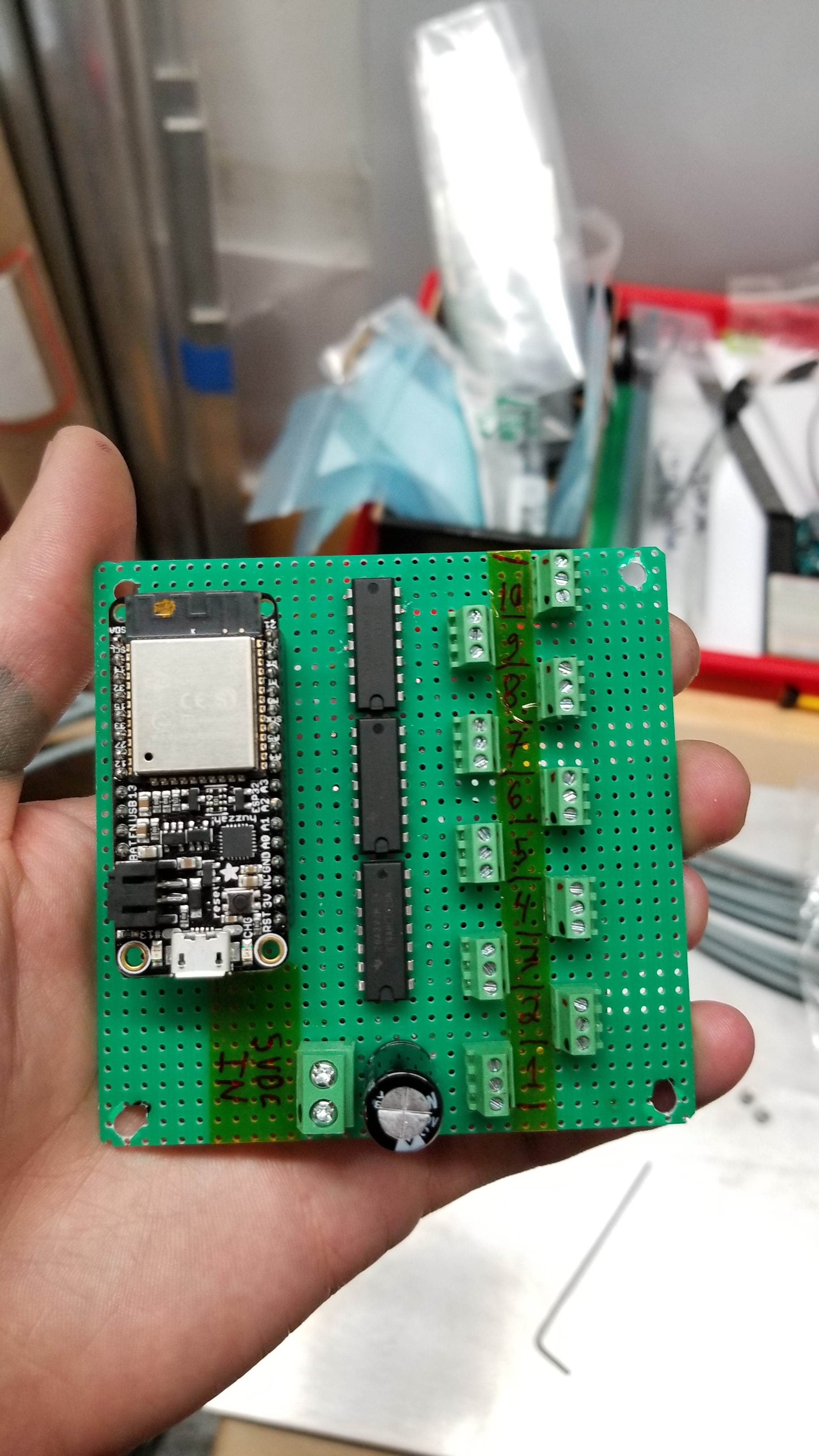
The controller itself is an ESP32 Feather from Adafruit along with a few logic level shifters, as well as a few screw terminals and a big fat cap.
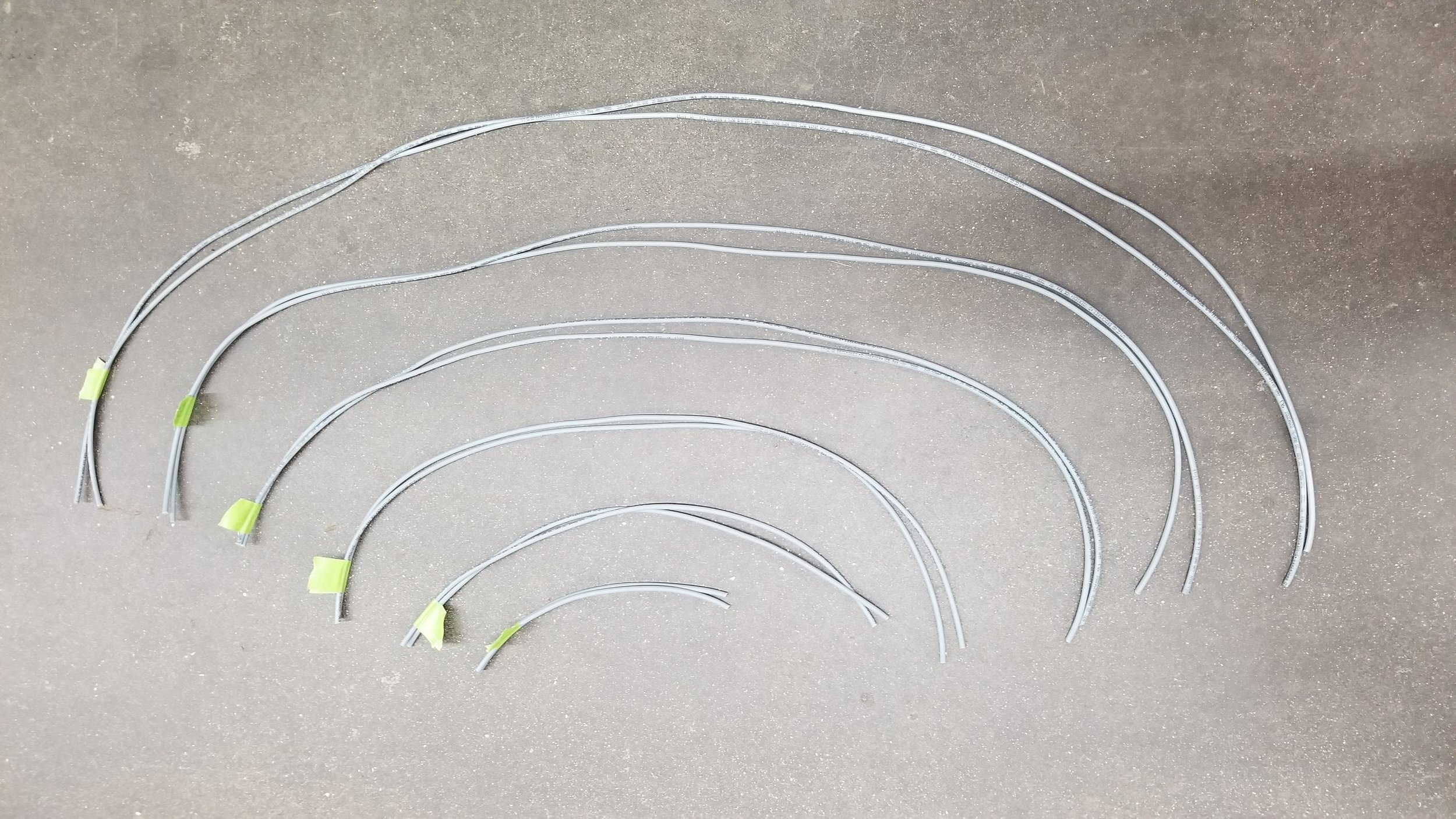
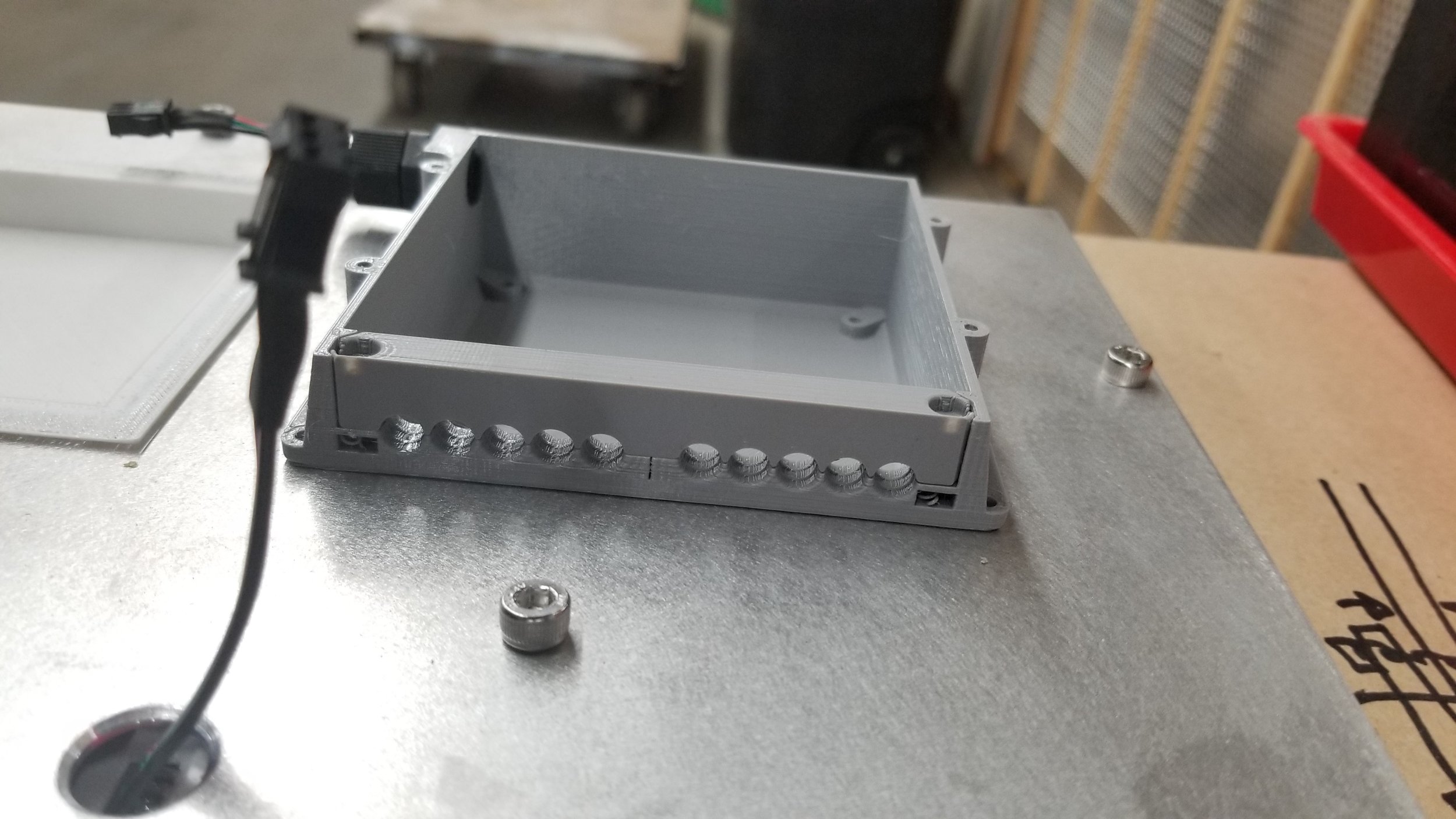
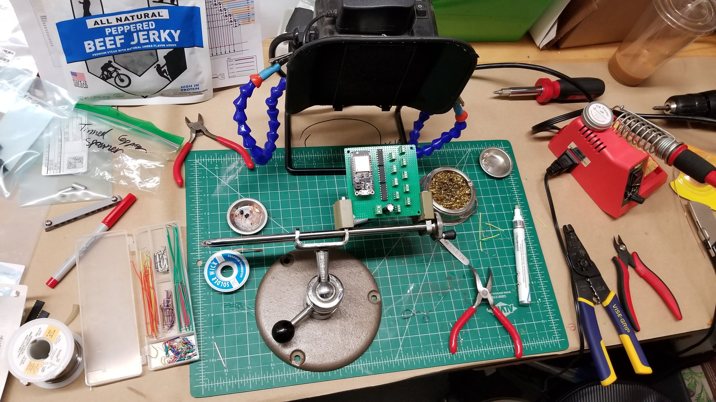
Not shown - the Fat Cap.
And with that wired, it was on to programming.
Oh man. This was a bit of a bear.
Ultimately, I already had the framework for the digit display code built around the code I’d used on the SLOWETRY project. It was a small matter to adapt if for a 7 segment display versus a 14 segment display. (Divide it in half, hah). The tricky part was keeping all the animations smooth. As the ESP32 is driving all the LEDs (16 per segment, 7 segments per digit (112), 10 digits in the display (1120 pixels)), and trying to do it in a buttery-smooth sort of way, I made the underlying animations pretty easy. Ultimately, it’s generating a single color per digit, and then running each digit to display through the 7 segment display processing series to find which segments are actually going to be displaying that color. It checks whether the pixel is on or off within the mapping of the segments, and if it’s on it assigns the pixel the digit’s color. If It’s off it assigns it to black and carries on. So, there was binary element to each pixel that the program needed to keep track of. As the standard Arduino boolean variable stores each boolean as an 8-bit datatype (Which is ridiculous), I ended up using a bit-boolean library which substantially lowered the programs impact on RAM.
Which was all well and good, except the ESP32 (At the time) didn’t support WS2812b’s too well. With the dual cores and priorities built into that processing, using the standard Adafruit Neopixel library just wouldn’t work. It would turn the LEDs on, but there would be random LEDs turning on and it looked noisy.
Testing it out on my test fixture. See the green LED’s?
After a few days of harried searching, I found the FastLED library, which ended up working wonderfully. I was able to get it to count!
But, it still wasn’t communicating with the internet. To show the proper count, the display needed to connect to the local wifi, connect to the web, navigate to the proper page where the count was displayed, identify the count within the page, clean up that string and convert it to a digit, and THEN parse it into the LED array to show it on the display.
The ESP made it simple to connect to the WiFi, just pass it the SSID and password and it takes over from there. From there, I used a library to load in the HTML page that was loaded, and knowing that the updated count was always the last line of text in the body of the page, I was able to reverse the loading of the page to only pull in the last line of text from the page, up until an underscore that served as a control character. I then converted the string stored into a long-long, as a standard long can only hold a 32 bit value, which means its only up to 4.29 billion combinations. I needed 10 billion minus 1. After that, it parses out the segments used to display that number on the digits, and then disconnects from WiFi until it’s ready to connect next.
As the source for the count of magic moments was only updated around 5 times a day, having the display checking the current count too often would be a waste of resources. Instead, based off of the time signature of the network it’s connected to, it re-connects to WiFi and polls the current count once every hour on the hour. That also allows for a bit of wiggle room should WiFi go out for a few minutes.
So, it all came together. And once it was setup, It worked well.
From there, all it needed was to be installed.
I elected to use a standard 1-3/8” Uni-Strut, as the area that it was to be installed into had supports spaced across the ceiling every 48” that I needed to span to connect into. The Uni-Strut allowed me to move around connection points and adjust the threaded rod that the display was hung off of. It worked perfectly…
And with that, I was done.
Or so I thought…
Turns out even though it was a dynamic display, it still had quite a bit static to it. As I came to discover, through some fluke of being installed hanging from the ceiling, the display would build up quite a static charge. After not touching it for more than 5-6 hours, it would generate enough charge to arc 3/4”, or (In my case) cause the LEDs to start glitching out and fail. It may have been the capacitance of having an aluminum backer attached to a plastic face, or something to do with the HVAC unit located on the roof above this piece, but it was failing overnight. After tracking down the level of static building up on the piece, I decided to just ground the whole of the display in such a way that no buildup should happen.
I purchased an IEC cord that had the grounding plug broken out. These are usually used in server racks where you need to ground the rack in addition to supplying power to a PC in the rack. I clipped off the eyelet and crimped on a spade connector, allowing me to make an extension for the ground that I ran all the way back to the aluminum carrier panel. Once this IEC cable was then plugged into the 5v power supply for the piece, the ground could wick up any static charge built up and put it straight to earth. Once I plugged it in, no more static. Problem solved.
Anyways this was a wonderful project and I learned a ton. I think the ESP32 is to become a staple of my projects in the future, as its speed and power for the price is just incredible. I hope I get to make more of these sorts of displays in the future.
Cheers,
Mac


